The penguin's motorcycling and Jeep blog

Showing posts with label v-strom. Show all posts

Friday, October 17, 2008

WIndshield for the 'Strom

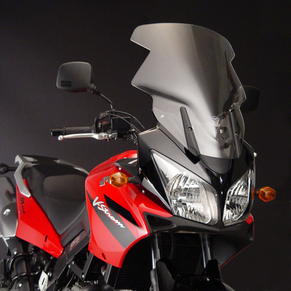
To deal with the upcoming winter rainy season I just ordered what must be the world's ugliest windshield for my Suzuki DL650 V-Strom: That is the National Cycle VStream. The weird cut-outs are to make room for the mirrors and the handguards on bikes that don't have bar-backs like mine, otherwise the windshield is too wide for the bike. The cut-outs also help with reducing buffeting behind the windshield, since the air coming around the cut-outs helps reduce the backpressure behind the shield.

We'll have to see what happens. This windshield was at least $80 cheaper than the other high-end windshield I was looking at, so hopefully it'll work. Otherwise I'll have to sell it off on Fleabay and fork out more money, bummer :-(.

-- Badtux the Motorcyclin' Penguin

Saturday, September 27, 2008

Scottoiler!

I just finished installing a Scottoiler on the Blackstrom. I'll add some photos to this post once I'm not so tired, but basically, here's how it went:

The first thing I had to do was find a place to put the reservoir. Finally I noticed that there was a plastic trim poprivet (the kind you push the center in to remove, then pop the center back out to re-insert, that holds two plastic trim pieces together) right beneath the rear left fender where an exhaust pipe might be if the Blackstrom had dual exhausts. I popped it out and looked at the mounting bracket for the reservoir and yep, the reservoir's mounting stud was almost exactly the same size as that hole. A couple of washers later, and the reservoir was mounted. Most people mount it inside the rear left fender rather than hanging under it, but I like it outside so I can glance at it to see if it needs filling and fill it up without taking the seat off. Besides, to put it inside the rear left fender I would have needed to take the plastics off, and that would have required taking the rear luggage rack off, which is a PITA...

The next thing was to route the vacuum line. The Scottoiler uses engine vacuum to open a plunger to let oil drip out onto the chain. That keeps all your chain oil from dripping out when the bike is off. I had to glue one guide onto the plastics in order to keep the vacuum line from flopping into the wheelwell. Oh well. It's hidden up under the fender, and from there the vacuum line goes through an already-existing hole in the plastics and forward to the forward throttle body, where it plugs into the throttle body sync port (previously covered with a vacuum cap) using the adapter in the kit. At some point in time I need to re-plumb this port with a "T" so you don't have to pull off the Scottoiler vacuum hose to sync the throttle bodies, but this is okay for now.

The last and final thing to do was to route the oil line. I routed it basically down the rear subframe member until reaching a point where I could hop it down to the swingarm, then of course to the side of the swingarm, then down underneath it until I could bend the nozzle so that the tip was just above the chain at the sprocket.

Once all that was done, I could prime it. I use GM Dexron III ATF as my chain lube in my Scottoiler on my KLR, so in the interests of keeping a common lube, I primed this Scottoiler with ATF also. Unlike the weird "Scott-oil", Dexron III is available for cheap at every Wally World and roadside Kwicky-mart in the USA, so it makes more sense to put ATF in the chain oiler if you intend to take long trips, as I do. So I shoved fluid into it using the sealed priming intake port until nice pink fluid started dripping onto the chain, then popped the cap and finished filling up the reservoir with ATF.

Tomorrow I'll need to calibrate the thing to have the correct number of drops per minute. It doesn't take much, I don't intend to ride this bike through the dirt so I just need enough slow drip drip drip to keep the chain o-rings moist and conditioned and keep the chain from rusting. Any more than that and it just makes a friggin' mess. But in case it's raining or I do go through the dirt or something, all I have to do is turn the dial turn make it drip faster, and there we go. A mess on the back of my bike is better than having a rusty chain, after all...

-- Badtux the Motorcyclin' Penguin

Saturday, September 20, 2008

Adding an electrical socket

One of the things I wanted for the Nightstrom was a way to pump up the tires using a small electric pump. See, it's always wise to air down your tires if you're going to ride down a gravel road, it makes your tires ride smoother, gives you more traction because they can conform to the rough road rather than just the tips of the rocks hitting your rubber, and it keeps the sharp rocks from slicing your tires up because your tires deform instead of slicing. But then once you hit pavement again you have to air your tires back up. Given that the tires on my V-Strom 650 want to be pumped up to 40PSI, doing that with a hand pump is a PITA.

Another thing I wanted was a socket on the side that I could power a heated vest with. A Powerlet socket seemed just the thing for both, since it had positive retention for a heated vest jack, but there is an adaptor to plug a cigarette-lighter-driven airpump into it. So I headed off to Easter Beaver and got the V-Strom rear electrical outlet kit. And here it is:

The first thing I did was put the bracket on. Here is the bracket(note: click on any picture to embiggen): The bracket fits behind the footpeg mount. There is also a washer/spacer (in the little baggie with the fuses in the first photo) that goes under the other footpeg mount bolt to space it out equally. The bolts were locked on with threadlocker, as is usual for this bike (Suzuki apparently got tired of bolts rattling loose so threadlocks *everything*), but unlike some bolts I didn't need to pull out the butane torch and heat these up to get'em out, the threadlock compound let loose fairly easily. So:

  1. Loosen both footpeg mount bolts by about the thickness of the bracket
  2. Take out the upper footpeg mount bolt (the one where the bracket goes).
  3. Clean the old dried-up threadlocker compound off with a brass wire brush
  4. Put fresh new blue threadlocker on it.
  5. Slide the bracket in, and then put the bolt back in through mount and hole in bracket and tighten it until just barely snugged.
  6. Take out the lower footpeg mount bolt, wirebrush it, and re-threadlock it.
  7. Slide the spacer back behind the lower footpeg mount until you can see through it to the threads in the frame.
  8. Tighten the lower footpeg mount bolt until snug, tighten the upper footpeg mount bolt until tight, then lower footpeg mount bolt until tight.
So here is the result:

And now that the bracket is installed, now I put the socket through the hole in the bracket, with the spacers, washers, and nuts in the order specified on a sheet of paper inside the little baggie. Once the socket was tight in the bracket, I inserted the rubber boot over the end of the wires, and then shoved the connector ends into the empty socket where they belonged, and plugged in the connectors to connect it to the wire to be run to the fuse panel. Then I ran all the wires up behind the side panel to the vicinity of the battery. Here is where we are at this stage:

Now, I have an auxiliary fuse panel, previously installed (sorry that I never finished talking about that, but I'm not quite satisfied with my installation yet, oh well!). So now it was time to hook the wires up. Always pull the main fuse to whatever fuse panel you're working with, or if there is no main fuse, disconnect the ground wire from the battery. In this case, I pulled my 30 amp main fuse for the auxiliary panel, then ran the new wires to the auxiliary panel, cut them to length, stripped, and inserted into the connectors on the fuse panel. Here is the result, before I put the cover back on the auxiliary panel. The new wire is the one hooked to the 15A circuit, which is a permanently-on circuit (this being a Centech AP2, where the first three circuits are switched and the two nearest the front are permanently-on). I hooked it to a permanently-on circuit because I don't want to have to start the bike to pump up the tires. Before I put the cover back on the Centech, I temporarily replaced the 30A main fuse, and tested the socket by, err, plugging the Powerlet-to-cigarette-lighter adaptor in then the air pump, and turning on the air pump. It worked! So then I took the 30A fuse back out, and put the cover back on the Centech. Here is the final result: The new wires go through the grommet into the underseat compartment, and you can see the empty main fuse holder towards the left of the photo near the negative pole of the battery. Behind that is the relay for the Centech AP2 so that the first three circuits will be on only when the ignition is on, this was another Eastern Beaver kit, it plug-and-plays once you find room for it, no cutting of the OEM wiring harness required. The three fuse holders immediately to the right of the relay (as we look at this photo) used to be spaced along the backside of the battery compartment on three molded-in pegs, but I cut the pegs off and shoved them over to the side to make room for the Centech relay.

And anyhow, that's the end of the story. Hopefully I'll get back to providing a tutorial on electrical work, but it's hard work, and I've been very busy recently due to a project at work. If you have any questions, just ask!

Thanks,
- Badtux the Electrifyin' Penguin

Sunday, September 7, 2008

Nevermore

Two Ravens
I bought a new pair of leather gloves with gel palms and knuckle protectors today, then took the Wee-strom for a ride. Forgot my camera, alas (not the only thing I forgot). Anyhow, I rode it in a loop, from South SF Bay to CA 17 to Santa Cruz then along CA 1 to Half Moon Bay, then back over the mountain and home again. Some things I figured out along the way:
  • The Madstad bracket and the OEM windshield makes a nice combination when it's all the way down and tilted all the way back. There's no buffeting and side winds just make the bike flop left and right a little, they don't move the bike around on the highway. There's plenty of air flow to help keep cool on a hot day like today, but there's no wind blast making things uncomfortable.
  • The highway pegs mounted on the Pat Walsh guards (courtesy of some slightly shorter mounting bolts from Orchard Supply Hardware, the ones that came with the pegs were a little too long to work without the bracket) work great. These particular pegs are very heavy and have rubber insulating pieces. The location of the pegs is perfect for stretching out when on the road, without putting you into an uncomfortable position.
  • The Suzuki gel seat is just too darned hard! Folks say that the Corbin seat is hard. My Corbin seat on my KLR broke in just fine, it's not hard, it's just firm. So anyhow, I have a Sargent seat on order (the Corbin for the V-Strom is too tall for me). The seat is shaped right, it would be comfortable if it wasn't so darned hard, but I think the only way it would be a good seat would be to take the cover off, remove the gel insert, and replace it with some firm foam that shapes to your butt like memory foam. Not to mention that the gel will roast your 'nads if you leave the seat out in the sun!
  • The Rox adjustable risers rock. My handlebars are *exactly* where I want them to be. I can lean forward into a semi-sportbike position and still have good control, I can relax upright and put my feet up on the highway pegs and the bars are just there, in the exact right location.
  • I need to get some of that motocross underwear. It's like bicycle shorts, except not as long in the legs and without that padding that keeps your 'nads wet on a motorcycle (since the tank blocks the air to the 'nads). Regular underwear simply has the seams in the wrong friggin' place to be comfortable for long rides on a motorcycle...
  • The BMW electrical plug for the GPS crapped out *again*. This is two long rides I've taken, and two rides that the GPS wiring went AWOL. I think I'm just going to hard-wire the bloody thing, this is getting ridiculous.
  • The Black Raven is a sweetheart of a motorcycle. She heels over into a bank without any complaints, holds her bank without a problem, and comes back upright with no problem. She's a bit fat and heavy to flick as easily as a sportbike but she handles fine for a bike of her heft. And that 90 degree V-twin engine is just sweet, sweet, sweet.
  • Still to do: Put on the automatic chain oiler (a must for long-distance travel especially in the rain), put on the side Powerlet outlet for use with the heated vest, put on the heated grips, and maybe install electronic cruise control. Maybe. I'm not convinced yet, electronic cruise control on a motorcycle is like that damned Powerlet plug for my GPS, something is always vibrating loose and making it quit and then it's just a pile of parts taking up space until you get to a garage somewhere so that you can diagnose it.
In the meantime, I need to take the Jeep to the car-wash to have last fall's dirt washed off of it and last falls' dirt vacuumed out of its carpets (its annual car wash, yippee!) and get some new windshield wiper blades front and back to the thing. A penguin's chores never seem to end...

-- Badtux the Ridin' Penguin

Wednesday, August 20, 2008

The never-ending electrical project done!

Got it all back together and it works. So I'll put together the remainder of the postings describing the project, and maybe enlighten you a bit about how electricity works while I'm at it. Next up, I add a socket on the side for the heated vest and air pump (that one doesn't get switched, unlike the one at the front), and then go looking for that mysterious heated grips connector up front and add my heated grips. That should pretty much do it for the electrical stuff, unless I add electronic cruise control, which has a fair amount of electrical work of its own...

-- Badtux the Electrifying Penguin

Tuesday, August 12, 2008

The never-ending electrical project

Last night I got about 45 minutes to work on the Nightstrom, my flat black 2008 Suzuki DL650 V-Strom. I gave up on relocating the ABS fuses and relay to behind the left side panel. It was too hard to get the left side panel off, requiring too much disassembly of the bike, and replacing those relays and fuses isn't something I want to spend hours doing on the side of a road (eep!). With the relays and fuses still relegated to their original general location behind the battery, I finally gave up on putting the new fuse panel immediately behind the battery. There just was not enough room there. Instead the new fuse panel will have to go in the owner's manual tray.

That decision made, I took some stick-on plastic hooks and moved the ABS fuses and ABS relay to a more compact configuration. They were originally hooked via rubber slots to tabs on a piece of plastic attached to the battery tray. I cut off that plastic extrusion of the battery tray and moved them back to the front side of the owner's manual tray, more to the left. This leaves me room to put the fuse panel relay alongside them in the space to the right of them.

So anyhow, I'm going to stick the fuse panel into the tray with velcro, rather than screws. That way I can more easily lift it when I want to screw new wires into it (otherwise it's damnably hard for my beady little penguin eyes to get a wire into the correct location on the panel). I ran out of velcro so I'm going to need to run to Radio Shack this afternoon and get some. I am taking photographs of everything I am doing, and will post a nice big summary when I'm done. Just remember that what you will see there leaves out all the mis-steps and false starts that thus far have characterized this project, heh :-).

-- Badtux the Electrifying Penguin

Sunday, August 10, 2008

Motorcycle wiring sucks

I am currently engaged in trying to get my fuse block installed on the Nightstrom. To do that, I had to first find a place to put the fuse block. I finally decided I could re-arrange the ABS relay and fuses into a more compact arrangement and put the fuse block in the area behind the battery where those are located. Now I have to fish the rear brake wire out from under the coolant reservoir and tap in to it for my relay that will turn the fuse block on and off, and find a place to put that relay. It's looking like I might have to take the rear rack off my bike to get the side cover off to find a place to put the relay. Which also requires taking the Givi luggage racks off the bike because they either block access to the rear rack bolts or are blocking the removal of the panel I need to take off.

All I wanted to do was install a simple wire harness and fuse block, not disassemble my bike! Oh well, at least I still have my KLR to ride to work tomorrow...

-- Badtux the Dissassembling Penguin

Saturday, July 26, 2008

Stone age vs. Digital age and the Nightstrom

Here's what I spent this morning doing: I spent this morning taking the Nightstrom to the Suzuki dealer for its 600 mile service. Yes, I, a motorcycle wrench of long standing, took my motorcycle to (sob) THE DEALER for servicing!

So why did I do this, when my Kawasaki KLR-650 has never darkened the interior of a dealer's door? Well, it's the stone age vs. the digital age. My KLR-650 is defiantly stone-age. It has one cylinder. The ignition has its own coil at the magneto and does not need the battery in any way to operate. It has a stone-age carburetor that is gravity-fed with no pumps or anything involved, as long as the bike is upright enough that the carb is below the gas petcock, the carb gets gas. If you kill the battery somehow, no problem -- just push-start the thing. The downside of course is that it makes about as much power as a riding lawn mower (34hp in actual dyno tests), has a top speed similar to a Ford Pinto, and gets fairly humdrum gas mileage for a 650cc motorcycle (around 40mpg).

But my new DL650 V-Strom is digital age all the way. You can't look up at the clocks and read off the odometer mileage when the bike is off. That's digital. You gotta turn the key on. You have a digital fuel gauge, digital temperature gauge, digital Antilock Braking System. The fuel pump is inside the gas tank and requires up to 40 watts of power to operate, and drives digital fuel injectors on digitally controlled throttle bodies. If you have no battery power you aren't going anywhere -- the injectors won't run, the fuel pump won't run, the stepper motors controlling the idle valves won't run, you're SOL. The upside is that you get 60 horsepower, a smooth power curve from idle to redline thanks to the oxygen sensor allowing the fuel injection to precisely map the fuel-air ratio at all throttle settings and RPM's, clean emissions thanks to the catalytic converter in the tailpipe, and even if you ride it fairly aggressively you still get 50mpg, and can get better if you keep your RPM's below 5,000 RPM (but that's boring!).

Now, for the most part I don't mind the fact that my Nightstrom is completely digital age. The upside is that it has tremendous power, excellent ridability, and gets great gas mileage. But one of the things required at 600 miles for a DL650 V-Strom in California is a throttle valve sync. And because idle is computer-controlled on the Nightstrom, this requires Suzuki's special computer to disable the computer-controlled idle and center the idle stepper motors on that computer-controlled throttle body. Then, and only then, can you adjust the idle air bypass screws so that a) each throttle body has equal vacuum and b) the bike is idling at the specified 1300 rpm when the idle stepper motors are centered. Anything else would be Just Wrong(tm).

See, here's the deal. Idle speed is controlled by the computer on this bike. There is a flap in each throttle body that allows more or less air to pass into the throttle body at idle. This flap is controlled by the idle stepper motor. When the bike is cold, the idle stepper motor will adjust the idle slightly upward at the same time that the injection system enrichens the mixture slightly. When you are at high altitude, again the idle stepper motor will adjust to give you slightly more air while the injectors lean out the mixture slightly (remember, we have an oxygen sensor down by the catalytic converter, so the injection system always knows how much fuel to inject to get ideal combustion).

So anyhow, under normal conditions, you want the idle stepper to be in the middle, so that it can open or close the idle air flaps as needed when conditions are *not* normal. Thus the need to use the special Suzuki computer to lock the idle stepper in the middle. If you try to adjust the idle air bypass screws without first locking the idle stepper in the middle, the computer will notice that you're giving a little more air to cylinder A that was showing more vacuum than cylinder B, and will tick the idle stepper downward to reduce the idle back down (since giving more air raised the idle to above 1300rpm). It is easily possible to get the idle stepper into such a position that it's no longer capable of adjusting idle. You can sorta compensate by giving a little less air to B at the same time as you give a little more air to A, which hopefully would avoid clicking the stepper, and I would do that if I was in the middle of Africa and didn't have Suzuki's special computer available to me, but there's no guarantees that this will keep the idle stepper centered when the bike is idling at 1300 rpm under normal conditions. The only guarantee is to use Suzuki's computer to lock the idle steppers in the center before you start twiddling the air screws.

So anyhow, that's the downside of the digital age: trips to the dealer (or potentially to an independent mechanic who happens to have that digital tool). Sigh. Computers. Talk about your love-hate relationship... I love the benefits of the thingies, but sometimes I do pine for the days of stone-age motorcycles where you didn't need much beyond a screwdriver, a big hammer, and a pair of pliers to fix pretty much anything. Luckily I have my KLR for when I'm pining for those days :-).

-- Badtux the Motorcyclin' Penguin

Saturday, June 28, 2008

A disappointment

This is a Pat Walsh Designs Engine Guard and Skid Plate combo for the Suzuki V-Strom 650. It took them over two weeks to get it to me after I ordered it -- it came in today, and I ordered it back on the 9th. When I called Pat yesterday he claimed that Paypal has not been sending him his email, which is possible, I suppose, the shipment does contain a copy of an email I sent several days ago re-forwarding Paypal's email to me, so obviously his people got my email, but did not reply to it so I had no idea what was going on. Anyhow, the skid plate is the plate. The engine guard bars are the curved bars. The cross bar is the mostly straight bar with the little zig-zag in it. It mounts sorta like this: Click the photo for a bigger picture. The curved bar mounts to the upper engine mount bolt (arrow), the cross bar, and to the skid plate. The skid plate mounts to the curved bar, and to one of the kickstand bracket bolts (lower left arrow). On the other side, the back of the skid plate mounts to the exhaust mount bracket, which is fairly sturdy but the exhaust mount bolt is sorta wimpy so that side isn't as well supported.

Unfortunately, one of the captive nuts welded into one end of the crossbar had a bad weld that impinged upon the thread area. The result was that when I tried to screw the bolt in, it seized. I had to use a pipe wrench on the crossbar and a 4-foot breaker bar to unscrew the bolt until it completely seized and I twisted its head off. This messed up the cross bar (the pipe wrench crushed it) and of course messed up the bolt, but at least I got this mess off my bike. This is the best photo I have of the damage (click on the photo for a bigger picture). You can see the welded-in captive nut, and the crushed area where I held it with the pipe wrench, and you can see the head of the bolt that I twisted off down below. The bolt twisted off at a point within the captive nut where apparently a bead of welding slag came to rest and jammed up the works -- this wasn't a case of me over-torquing a bolt (the bolt would have broken off at the point where head and shaft meet in that case).

I will call Pat on Monday and see if he can fix me up with a new crossbar and bolt in a timely manner. Needless to say I was using the sort of language in my garage that is not fit for polite company. Especially since I had to take that blasted kickstand bolt off again and it was partially hidden by the skid plate, meaning I had to use a box wrench and very slowly one tiny bit at a time unbolt it, plus my garage was hot so I was sweating like a pig... so anyhow, my bike is unprotected again, stripped of all skid plate and crash bars. Sigh.

-- Badtux the Still-unprotected Penguin

Thursday, June 26, 2008

And what were *you* doing at 2AM?

Me, I was working on my Suzuki V-Strom 650 ABS, adding a Powerlet socket to the Rick's Shelf using the Left Front Panel socket kit from Eastern Beaver. I also mounted the Garmin Zumo 550 GPS's RAM ball to the handlebar and used the Garmin Zumo to Powerlet short power cord to plug it in. I also have an adaptor so I can power a regular cigarette-lighter-type electric air pump off of this socket to air up my tires.

The core problem is that I had to take off the gas tank and this was the first time I ever took off the gas tank so it took me a while to get everything off. To take off the gas tank, here's what I did:

  1. Take off the side gas tank panels by unscrewing the one screw at the front that holds them on and popping them out of their rubber donuts that holds the rear part of the panels on.
  2. Remove the rearmost screws on the side fairing panels (there will be two of them).
  3. Locate the center fairing strip between the gas tank and the steering column, and the two plastic retainer buttons at the front. Push in the center peg of those buttons until they make a "snap" sound (use a ballpoint pen or something), and remove the buttons.
  4. Remove the center fairing strip -- the sides just snap under the side fairing, you should be able to pop the side fairings outward a little and it'll just come out.
  5. Remove the seat
  6. Grab a 12mm wrench and remove the single bolt holding the back of the tank on
  7. Take the silver tank prop that serves as the top of the tank mount and lift the tank up enough to prop the tank up with it. DO NOT TRY TO LIFT IT HIGHER THAN THE PROP, there is a stop on the pivot hinge up front that you can damage if you try to lift it against the stop.
  8. Unplug the fuel gauge wire on the left side
  9. Unplug the fuel line on the left side
  10. Unplug the overflow line on the right side (just pop it off the tank)
  11. Unplug the charcoal canister condensate return line on the right side. (Was easier for me to pop it off the frame mounted fitting than to pop it off the tank, also kept clear which line went where).
  12. Remove the prop and let the tank back down. Grab a pair of 10mm wrenches (I had one socket wrench and one box-end wrench), and remove the pivot bolt at the front of the tank.
  13. Lift the tank and slide it backward off its rubber mounts up front, then lift and place aside.
Now you have the top of the bike naked and can just lay the wire from the battery all the way to the front of the bike on top of the existing wires. The only exception is that I ran it around the side of the head instead of through the box and clamp behind the radiator then the hole at the front of the frame. I then plugged it into the Powerlet outlet (which I had previously installed on the dashboard then installed the dashboard), and moved the steering from lock to lock to insure that I had enough slack. I did -- barely. I zip-tied the front in place, checked my steering slack again, still okay, then zip-tied the rest in place all the way back to the battery.

This kit was intended for the left dashboard panel, and was cut to be very slightly longer than required for that purpose. Going rightward and requiring some slack for turning the steering wheel means that I only barely have enough wire to get back to the battery. When I add a fuse panel in the tray behind the battery, I will have to cut off the battery end of this kit and add some longer wires to get to the fuse panel using Posilocks or regular crimp connectors. So it goes.

Now, what took me so long: I was following the directions in the factory service manual, which calls for removing the front side cowling panels also as part of removing the fuel tank. To remove the front side cowling panels, take out all the visible screws. Next you have to remove the chin cowling underneath the headlights. This is done by pushing in the center of a dozen of those button-type fasteners and removing them, then removing two screws hidden deep in the wells of those fake air inlets. You can then wiggle the chin cowling out. Then you'll find out why we had to remove the chin cowling -- there's two more screws hidden behind the chin cowling holding on the side panels. Remove those screws. Then slide the side panels *forward* to get them out of their little rubber donut thingies, and when you feel them "pop" out of the little donut thingy wiggle them out from under the top panel (still sliding forward a bit). Then you'll have a nice open space to work in with no side panels in the way, which I suppose is why the service manual calls for removing these.

Anyhow, it's nowhere near as arduous a process as pulling all the plastics on my old Kawasaki Concours touring bike (now that bike had a lot of plastic on it!), but it was my first time doing it, so I was going very slow and careful. So that's why it took me four hours to do all this yanking of plastics, pulling the tank, running the wire on top of the existing wires, then putting it all back together again, and why I was in my garage until 2am last night. I wanted to ride that bike to work today. And did :-).

-- Badtux the Wrenchin' Penguin

Thursday, June 19, 2008

The Menagerie

The Silver Demon, so-called because it whispered in my ear, "Buy me! Buy me!" until I did: The Demon is a 2006 Jeep Wrangler Unlimited with a 2" spacer lift, 32" tires, and an Aussie Locker in the front axle. This was the last year of the classic Jeep TJ design and 4.0L inline 6 engine that could trace its heritage to the Rambler six's of the 1960's. It is slow, crude, evil-handling, drinks gas like it's going out of style, reliable as dirt as long as you keep on top of the maintenance, and it'll go anywhere reasonable for a 4x4 to go, and some places that aren't -- I have a couple of dents on the underside to prove the latter.

Next:

The Green Mule, so-called because, well, you'll see: The Mule is a 2002 Kawasaki KLR-650 dual-sport, outfitted here for some serious desert expeditioning. With the 7 gallon gas tank and 40mpg fuel economy it'll go over 250 miles on a tank of gas in relative comfort. The KLR is a crude and simple design that will run on any gasoline capable of being called "gas", is fixable with duct tape and a BFH (Big Fuckin' Hammer), and reliable as dirt. It's main problems are a) very weak on power (as in, top speed of about 75mph loaded down like the picture slowing down to about 50mph on long mountain grades), b) a ton of vibration, and c) a feeble headlight that fireflies laugh at. Unfortunately fixing parts a and b is very expensive and part c is unfixable without dumping the OEM headlight cluster entirely because the square headlight reflector simply won't produce an acceptable headlight pattern. Plus the KLR lacks the electrical generator capacity to run a high wattage bulb even if you did dump the OEM headlight and fairing.

Next:

The Wabs: Sorry I don't have a better picture yet, I just brought it home and this is the best that I can do in my garage. This is a 2008 Suzuki DL650AK8 V-Strom ABS. It is a sweet bike that is comfortable for the solo tourer when equipped with hard luggage and a big windshield (which this one will be), but still lightweight enough to be a fun commuter in the city when you strip the luggage off and run with the small OEM windshield. It has nearly twice the horsepower of the KLR and headlights that'll light up the night, especially now that I've put Phillips +50 H4 bulbs in there -- twice the headlight power of my KLR, with much better reflectors that put the light where it needs to be. The Weestrom (as the 650 V-Strom is nicknamed) has only one real weakness as a light tourer, and that's a lack of electrical power. You can run heated grips and a heated jacket liner, and a couple of light electronic gadgets like a GPS and an XM radio, and that's pretty much it. But you don't need auxiliary lights with the excellent headlights that the Weestrom has, so that's not a real problem. The Wee has only one big problem, and that problem is a serious lack of personality -- it is a pleasant bike that is good at everything but doesn't have the character of the KLR or Jeep. On the upside it gets 60mpg due to the more modern fuel-injected engine and while it has all the personality of a blender, it is as reliable as one too.

So that's the menagerie. More on them as we go along...

-- Badtux the Motorin' Penguin

Wednesday, June 18, 2008

Adding a GIVI topbox mount to V-Strom 650

This is how to add a Givi hard luggage topbox mount to a 2008 Suzuki V-Strom 650. The Givi kit is the E528 plate kit. It should be identical on everything V-Strom.

When you open the Givi box and unpack the kit, you find this: There are the two brackets that mount on the OEM luggage rack, the top plate that mounts to the brackets, and the hardware packet with all the screws for doing this. There's also an insert (the hard plastic thing), but I never put that on because it makes it hard to take the top plate off when necessary (remember, you have to take the top plate off to get to the luggage rack bolts, and you have to take the luggage rack off to get into the side covers to do things like, e.g., add brake fluid to the rear brake).

To do this task easily, you need these tools: From left to right: a 5mm allen wrench, a 4mm allen wrench, a 10mm open-end wrench, a tube of blue (medium) thread-locker, a pair of bent-nose pliers, a pair of scissors, and a 10mm socket wrench. You can actually do this job with the contents of your Suzuki toolkit plus the thread locker, but it's a lot easier with better-quality tools.

Okay. now here's the ground rules. There's other ways to do some of this. For example, I will take the luggage rack off. But someone with smaller fingers or better eyesight may just need to loosen the luggage rack screws. The way I'm going to do it is the easiest way (not necessarily the way I *actually* did it, mind you, but the way I'd do it again!).

So here we go:

Remove the seat.
Remove the luggage rack by unbolting the following four bolts with your 10mm socket wrench.

Place the rack on old newspaper or some other surface where it won't get scratched up, and remove the rubber top cover on the luggage rack. There are five rubber nubs holding it in. To remove one of the rubber nubs, take the bent-nose pliers and use them to tuck one edge of the flange on the backside into the hole, while at the same time you pull on the other side. If you keep tucking pieces of the flange into the hole while tugging on the other side, eventually the whole thing will pop out. Repeat until all five are out, and lay the rubber top cover aside. (Sorry I have no picture of me doing this, hard for me to take pictures when doing something that takes two hands plus my knees!).

Once the rubber cover is off, we're ready to mount the brackets onto it. Here is the hardware we need to mount the brackets. Note that the FLAT-sided bracket goes on the back. The ANGLE-sided bracket goes on the front. Assemble the hardware as such:

Round-top 4mm allen-head screws with washers on top, washers then the bright-colored 10mm ny-lock nuts on the bottom. Here we are going to put the front bracket on first, which is the bracket with the ANGLED sides. The rear bracket is the one with the FLAT sides. You only need to snug up the bolts, you don't need to twist the heads off, remember we have nylock nuts here which won't come off easily. Note that the front bracket is supposed to point the other way, towards the front. Having it this way moves the mounting plate and topbox backward slightly and gives more room to the passenger, but at the expense of making the top plate harder to mount (since the top-plate nuts are hidden behind the bracket to a certain extent). Experiment to see what works best for you -- this is motorcycle science, not rocket science, and there's no One True Way.

Now bolt the rack with brackets back onto the bike. Put a couple of drops of blue thread locker on each of the long 10mm bolts when you snug them down. Thus far I have not found a Suzuki spec on what these things are supposed to be torqued to...

Now place the plastic Givi mount on top of the brackets so that you can see the bracket's mounting holes through the diamond-shaped holes in the mount. Drop a diamond-shaped silver plate into each of the diamond-shaped holes and position so you can see the mounting bracket holes through the holes in the silver plates. Assemble a 5mm allen head screw and washer, and shove through the hole in the plate and through the hole in the bracket. Now, using your 10mm open-head wrench, take the black nylock nut and position it under the plate next to the screw, lift the screw from the top and then shove the nut into place with your open-head wrench and jam the screw back down onto it. Tighten a few threads using the 5mm allen wrench on top and the 10mm open head wrench on bottom. Repeat for all screws. Now, tighten all four corners so that the nuts are barely touching the brackets, and then position the top plate to your desired position. Snug down the allen-head screws. You're now done! Note -- I never put the smooth cover that says "Givi" onto the Givi mount. It makes it harder to take the top plate off, and the diamond-shaped holes in the Givi top-plate give places to poke bungee cords through the thing when you're using it as a luggage rack rather than a luggage mount. This is how I leave it. And here is my Givi E45 mounted on it:

My SOLAS tape is really doing its job of shining, eh?!

-- Badtux the Wrenchin' Penguin